
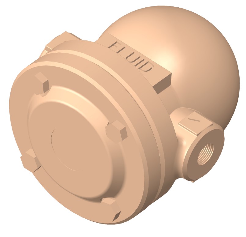
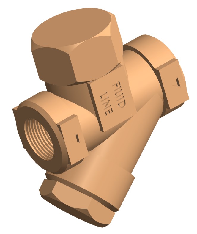
Looking for FLUID LINE products and services?
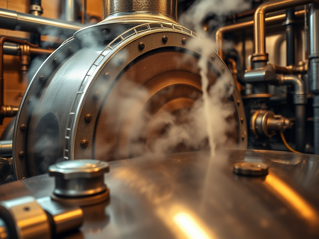
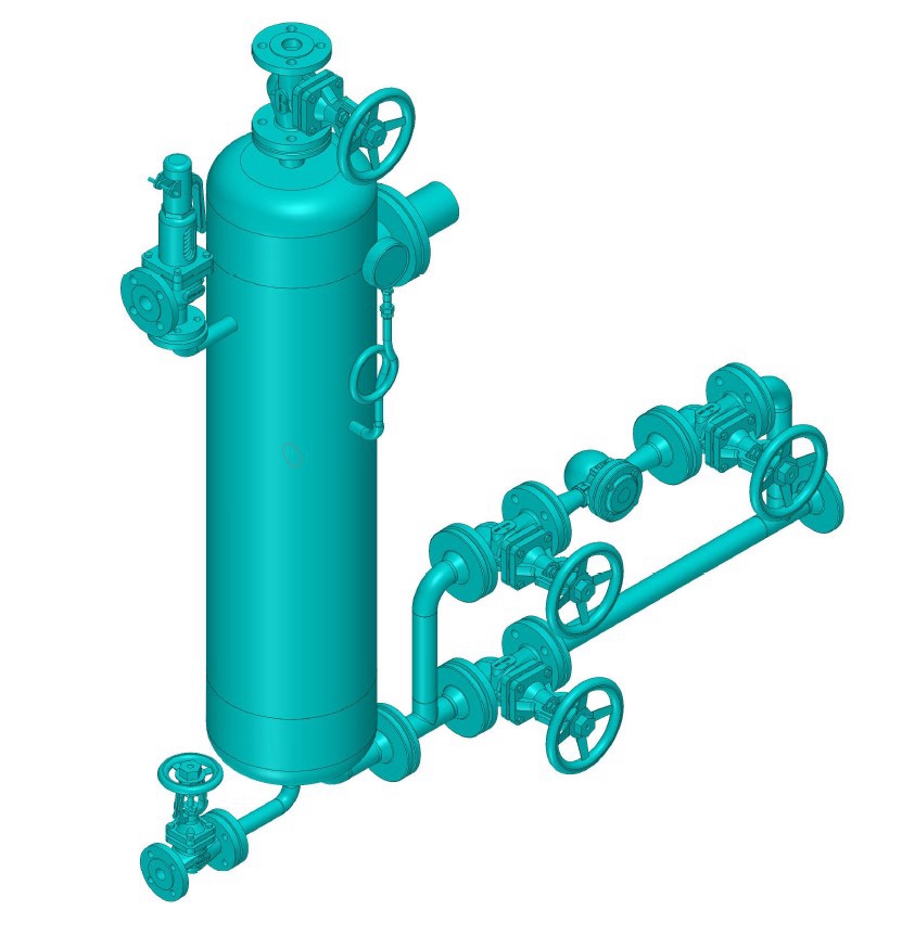
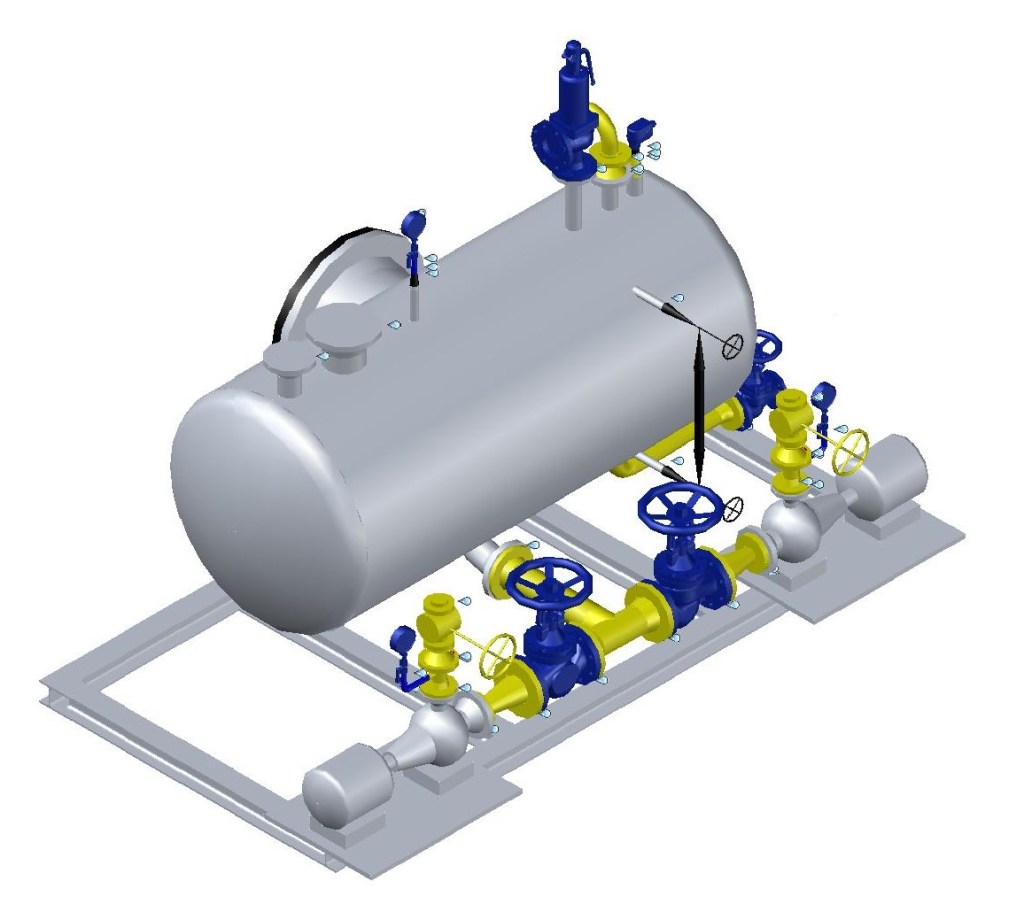
หาก Steam Trap ทำงานไม่ดี (เช่น ติดขัด
หาก Steam Trap ทำงานไม่ดี (เช่น ติดขัดหรือเสีย) และไม่สามารถระบายคอนเด็นเสท (Condensate) ออกจากระบบแลกเปลี่ยนความร้อนได้อย่างมีประสิทธิภาพ จะส่งผลกระทบต่อระบบดังนี้:
ผลกระทบที่เกิดขึ้น
- ประสิทธิภาพการแลกเปลี่ยนความร้อนลดลง
- คอนเด็นเสทที่ค้างอยู่ในระบบจะกลายเป็นฉนวนความร้อน (Thermal Insulator) ปิดกั้นไม่ให้ไอน้ำสัมผัสกับพื้นผิวแลกเปลี่ยนความร้อนโดยตรง
- ทำให้อัตราการถ่ายเทความร้อนลดลง Product อาจไม่ได้รับความร้อนเพียงพอ
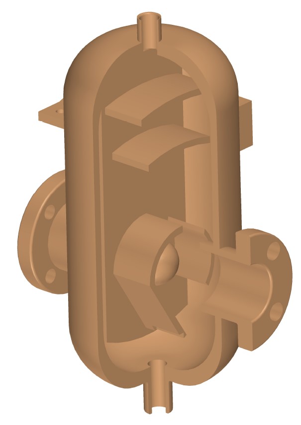
- เกิด Water Hammer
- คอนเด็นเสทที่สะสมในท่อไอน้ำอาจถูกพัดพาไปด้วยความเร็วสูงของไอน้ำ ทำให้เกิด Water Hammer ซึ่งสร้างแรงกระแทกทำลายท่อและอุปกรณ์
- เพิ่มความดันในระบบ
- คอนเด็นเสทที่ค้างอยู่จะลดพื้นที่ว่างในระบบ ทำให้ความดันในระบบเพิ่มขึ้น อาจทำให้อุปกรณ์เสียหายหรือเกิดการรั่วไหล
- ลดอายุการใช้งานของอุปกรณ์
- คอนเด็นเสทที่ค้างอยู่จะทำให้เกิดการกัดกร่อน (Corrosion) ในท่อและอุปกรณ์
- อุณหภูมิที่ไม่สม่ำเสมออาจทำให้วัสดุเกิดความเครียดทางความร้อน (Thermal Stress)
- สิ้นเปลืองพลังงาน
- ไอน้ำไม่สามารถถ่ายเทความร้อนได้เต็มที่ ทำให้ต้องใช้ไอน้ำมากขึ้นเพื่อให้ได้ผลลัพธ์เท่าเดิม
วิธีการแก้ปัญหา
- ตรวจสอบและบำรุงรักษา Steam Trap
- ตรวจสอบ Steam Trap เป็นประจำเพื่อให้มั่นใจว่าทำงานได้อย่างถูกต้อง
- ใช้เครื่องมือเช่น Ultrasonic Leak Detector เพื่อตรวจสอบการทำงาน
- ทำความสะอาดหรือเปลี่ยน Steam Trap ที่เสียหาย
- ติดตั้ง Steam Trap ที่เหมาะสม
- เลือก Steam Trap ให้เหมาะกับประเภทของระบบและปริมาณคอนเด็นเสท
- ตัวอย่าง Steam Trap ที่นิยมใช้:
- Thermodynamic Trap: เหมาะกับระบบที่มีความดันสูง
- Float Trap: เหมาะกับระบบที่มีคอนเด็นเสทปริมาณมาก
- เพิ่มการระบายคอนเด็นเสท
- ติดตั้ง Drip Leg (ท่อดักคอนเด็นเสท) ก่อน Steam Trap เพื่อช่วยดักและระบายคอนเด็นเสทได้ดีขึ้น
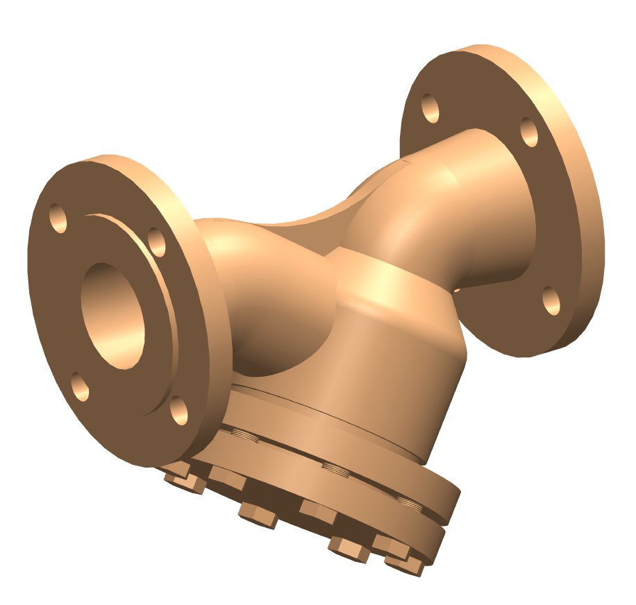
- ใช้ Strainer ก่อน Steam Trap เพื่อป้องกันเศษสิ่งสกปรกอุดตัน
- ปรับปรุงระบบท่อ
- ตรวจสอบให้ท่อไอน้ำมีความลาดเอียง (Slope) ที่เหมาะสม (ประมาณ 1:100) เพื่อให้คอนเด็นเสทไหลไปยังจุดระบายได้ง่าย
- หลีกเลี่ยงการเดินท่อที่ซับซ้อนเกินไป
- ติดตั้งระบบควบคุมอัตโนมัติ
- ใช้ Automatic Drain Valve หรือ Condensate Recovery System เพื่อระบายคอนเด็นเสทอัตโนมัติและนำกลับมาใช้ใหม่
- ตรวจสอบและปรับปรุงกระบวนการ
- ตรวจสอบอุณหภูมิและความดันในระบบเป็นประจำ
- ปรับปรุงกระบวนการผลิตเพื่อลดการเกิดคอนเด็นเสทที่ไม่จำเป็น
ตัวอย่างการแก้ไขในอุตสาหกรรม
- อุตสาหกรรมอาหาร: หากระบบแลกเปลี่ยนความร้อนใช้ในการฆ่าเชื้อขวดนม และ Steam Trap ทำงานไม่ดี จะทำให้ขวดนมไม่ได้รับความร้อนเพียงพอ อาจทำให้ผลิตภัณฑ์ไม่ได้มาตรฐาน
- แก้ไข: เปลี่ยน Steam Trap เป็นแบบ Float Trap และเพิ่ม Drip Leg เพื่อระบายคอนเด็นเสทได้ดีขึ้น
- อุตสาหกรรมยา: หากระบบแลกเปลี่ยนความร้อนใช้ในกระบวนการฆ่าเชื้ออุปกรณ์ทางการแพทย์ และเกิด Water Hammer อาจทำให้อุปกรณ์เสียหาย
- แก้ไข: ติดตั้ง Strainer และตรวจสอบ Steam Trap เป็นประจำ
สรุป
การที่ Steam Trap ระบายคอนเด็นเสทได้ไม่ดีจะส่งผลเสียต่อระบบแลกเปลี่ยนความร้อนหลายด้าน ทั้งประสิทธิภาพการทำงาน ความปลอดภัย และอายุการใช้งานของอุปกรณ์ การแก้ไขต้องเริ่มจากการตรวจสอบและบำรุงรักษา Steam Trap ให้ทำงานได้เต็มประสิทธิภาพ รวมถึงปรับปรุงระบบท่อและกระบวนการผลิตให้เหมาะสม!
หรือเสีย) และไม่สามารถระบายคอนเด็นเสท (Condensate) ออกจากระบบแลกเปลี่ยนความร้อนได้อย่างมีประสิทธิภาพ จะส่งผลกระทบต่อระบบดังนี้:

ผลกระทบที่เกิดขึ้น
- ประสิทธิภาพการแลกเปลี่ยนความร้อนลดลง
- คอนเด็นเสทที่ค้างอยู่ในระบบจะกลายเป็นฉนวนความร้อน (Thermal Insulator) ปิดกั้นไม่ให้ไอน้ำสัมผัสกับพื้นผิวแลกเปลี่ยนความร้อนโดยตรง
- ทำให้อัตราการถ่ายเทความร้อนลดลง Product อาจไม่ได้รับความร้อนเพียงพอ
- เกิด Water Hammer
- คอนเด็นเสทที่สะสมในท่อไอน้ำอาจถูกพัดพาไปด้วยความเร็วสูงของไอน้ำ ทำให้เกิด Water Hammer ซึ่งสร้างแรงกระแทกทำลายท่อและอุปกรณ์
- เพิ่มความดันในระบบ
- คอนเด็นเสทที่ค้างอยู่จะลดพื้นที่ว่างในระบบ ทำให้ความดันในระบบเพิ่มขึ้น อาจทำให้อุปกรณ์เสียหายหรือเกิดการรั่วไหล
- ลดอายุการใช้งานของอุปกรณ์
- คอนเด็นเสทที่ค้างอยู่จะทำให้เกิดการกัดกร่อน (Corrosion) ในท่อและอุปกรณ์
- อุณหภูมิที่ไม่สม่ำเสมออาจทำให้วัสดุเกิดความเครียดทางความร้อน (Thermal Stress)
- สิ้นเปลืองพลังงาน
- ไอน้ำไม่สามารถถ่ายเทความร้อนได้เต็มที่ ทำให้ต้องใช้ไอน้ำมากขึ้นเพื่อให้ได้ผลลัพธ์เท่าเดิม
วิธีการแก้ปัญหา
- ตรวจสอบและบำรุงรักษา Steam Trap
- ตรวจสอบ Steam Trap เป็นประจำเพื่อให้มั่นใจว่าทำงานได้อย่างถูกต้อง
- ใช้เครื่องมือเช่น Ultrasonic Leak Detector เพื่อตรวจสอบการทำงาน
- ทำความสะอาดหรือเปลี่ยน Steam Trap ที่เสียหาย
- ติดตั้ง Steam Trap ที่เหมาะสม
- เลือก Steam Trap ให้เหมาะกับประเภทของระบบและปริมาณคอนเด็นเสท
- ตัวอย่าง Steam Trap ที่นิยมใช้:
- Thermodynamic Trap: เหมาะกับระบบที่มีความดันสูง
- Float Trap: เหมาะกับระบบที่มีคอนเด็นเสทปริมาณมาก
- เพิ่มการระบายคอนเด็นเสท
- ติดตั้ง Drip Leg (ท่อดักคอนเด็นเสท) ก่อน Steam Trap เพื่อช่วยดักและระบายคอนเด็นเสทได้ดีขึ้น
- ใช้ Strainer ก่อน Steam Trap เพื่อป้องกันเศษสิ่งสกปรกอุดตัน
- ปรับปรุงระบบท่อ
- ตรวจสอบให้ท่อไอน้ำมีความลาดเอียง (Slope) ที่เหมาะสม (ประมาณ 1:100) เพื่อให้คอนเด็นเสทไหลไปยังจุดระบายได้ง่าย
- หลีกเลี่ยงการเดินท่อที่ซับซ้อนเกินไป
- ติดตั้งระบบควบคุมอัตโนมัติ
- ใช้ Automatic Drain Valve หรือ Condensate Recovery System เพื่อระบายคอนเด็นเสทอัตโนมัติและนำกลับมาใช้ใหม่
- ตรวจสอบและปรับปรุงกระบวนการ
- ตรวจสอบอุณหภูมิและความดันในระบบเป็นประจำ
- ปรับปรุงกระบวนการผลิตเพื่อลดการเกิดคอนเด็นเสทที่ไม่จำเป็น
ตัวอย่างการแก้ไขในอุตสาหกรรม
- อุตสาหกรรมอาหาร: หากระบบแลกเปลี่ยนความร้อนใช้ในการฆ่าเชื้อขวดนม และ Steam Trap ทำงานไม่ดี จะทำให้ขวดนมไม่ได้รับความร้อนเพียงพอ อาจทำให้ผลิตภัณฑ์ไม่ได้มาตรฐาน
- แก้ไข: เปลี่ยน Steam Trap เป็นแบบ Float Trap และเพิ่ม Drip Leg เพื่อระบายคอนเด็นเสทได้ดีขึ้น
- อุตสาหกรรมยา: หากระบบแลกเปลี่ยนความร้อนใช้ในกระบวนการฆ่าเชื้ออุปกรณ์ทางการแพทย์ และเกิด Water Hammer อาจทำให้อุปกรณ์เสียหาย
- แก้ไข: ติดตั้ง Strainer และตรวจสอบ Steam Trap เป็นประจำ
สรุป
การที่ Steam Trap ระบายคอนเด็นเสทได้ไม่ดีจะส่งผลเสียต่อระบบแลกเปลี่ยนความร้อนหลายด้าน ทั้งประสิทธิภาพการทำงาน ความปลอดภัย และอายุการใช้งานของอุปกรณ์ การแก้ไขต้องเริ่มจากการตรวจสอบและบำรุงรักษา Steam Trap ให้ทำงานได้เต็มประสิทธิภาพ รวมถึงปรับปรุงระบบท่อและกระบวนการผลิตให้เหมาะสม!
เกิดอะไรขึ้นกับท่อส่งไอน้ำนี้
!!!!อันตราย !!!!!
การที่ท่อส่งไอน้ำเกิด รอยยกตัวหรือรอยขยับจาก Support (จุดรองรับท่อ) อาจเกิดจากหลายสาเหตุ ซึ่งส่วนใหญ่เกี่ยวข้องกับ การขยายตัวทางความร้อน (Thermal Expansion) หรือ การติดตั้ง Support ที่ไม่เหมาะสม ทำให้ท่อไม่สามารถขยายตัวได้อย่างอิสระและเกิดความเค้น (Stress) สูงขึ้นจนทำให้ท่อยกตัวหรือเคลื่อนที่ออกจาก Support
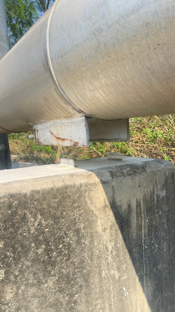
มาดูสาเหตุที่เป็นไปได้และวิธีแก้ไขกันครับ:
สาเหตุหลักที่ทำให้ท่อยกตัวจาก Support:
- การขยายตัวทางความร้อน (Thermal Expansion):
- ท่อส่งไอน้ำจะขยายตัวเมื่อได้รับความร้อน หากระบบ Support ไม่ได้ออกแบบมาเพื่อรองรับการขยายตัวนี้ ท่ออาจยกตัวหรือเคลื่อนที่ออกจาก Support
- อาการ: ท่อยกตัวหรือเคลื่อนที่ออกจาก Support เมื่อไอน้ำร้อนไหลผ่าน
- วิธีแก้ไข:
- ติดตั้ง Expansion Joint หรือ Loop Expansion เพื่อรองรับการขยายตัวของท่อ
- ตรวจสอบและปรับตำแหน่ง Support ให้เหมาะสมกับการขยายตัวของท่อ
- Support ติดตั้งไม่เหมาะสม:
- หาก Support ติดตั้งไม่แข็งแรงหรือไม่เหมาะสมกับน้ำหนักและขนาดของท่อ อาจทำให้ท่อยกตัวหรือเคลื่อนที่ได้
- อาการ: ท่อยกตัวหรือเคลื่อนที่ออกจาก Support
- วิธีแก้ไข:
- ตรวจสอบและปรับปรุงการติดตั้ง Support ให้แข็งแรงและเหมาะสมกับน้ำหนักท่อ
- ใช้ Support ที่สามารถรองรับการขยายตัวทางความร้อนได้ เช่น Spring Support หรือ Constant Load Support
- การสั่นสะเทือน (Vibration):
- การสั่นสะเทือนจากระบบไอน้ำหรืออุปกรณ์อื่น ๆ อาจทำให้ท่อขยับและยกตัวออกจาก Support
- อาการ: ท่อยกตัวหรือเคลื่อนที่ออกจาก Support และอาจมีเสียงดังจากการสั่นสะเทือน
- วิธีแก้ไข:
- ติดตั้ง Vibration Damper หรือ Snubber เพื่อลดการสั่นสะเทือน
- ตรวจสอบและแก้ไขสาเหตุของการสั่นสะเทือนในระบบ
- การสึกหรอหรือชำรุดของ Support:
- Support ที่สึกหรอหรือชำรุดอาจไม่สามารถรองรับท่อได้อย่างมีประสิทธิภาพ ทำให้ท่อยกตัวหรือเคลื่อนที่
- อาการ: ท่อยกตัวหรือเคลื่อนที่ออกจาก Support
- วิธีแก้ไข:
- ตรวจสอบและเปลี่ยน Support ที่ชำรุด
- การออกแบบระบบท่อไม่เหมาะสม:
- หากระบบท่อไม่ได้ออกแบบมาเพื่อรองรับการขยายตัวทางความร้อนหรือน้ำหนักของท่อ อาจทำให้ท่อยกตัวหรือเคลื่อนที่
- อาการ: ท่อยกตัวหรือเคลื่อนที่ออกจาก Support
- วิธีแก้ไข:
- ปรับปรุงการออกแบบระบบท่อให้เหมาะสมกับการขยายตัวทางความร้อนและน้ำหนักท่อ
- ปรึกษาวิศวกรเพื่อออกแบบระบบท่อใหม่หากจำเป็น
ขั้นตอนการตรวจสอบและแก้ไข:
- ตรวจสอบการขยายตัวทางความร้อน:
- วัดการขยายตัวของท่อเมื่อได้รับความร้อนและตรวจสอบว่า Support สามารถรองรับการขยายตัวนี้ได้หรือไม่
- ตรวจสอบการติดตั้ง Support:
- ตรวจสอบว่า Support ติดตั้งอย่างแข็งแรงและเหมาะสมกับน้ำหนักและขนาดของท่อ
- ตรวจสอบการสั่นสะเทือน:
- ตรวจสอบว่ามีการสั่นสะเทือนในระบบหรือไม่ และแก้ไขสาเหตุของการสั่นสะเทือน
- ตรวจสอบสภาพของ Support:
- ตรวจสอบ Support ว่าชำรุดหรือสึกหรอหรือไม่ และเปลี่ยนใหม่หากจำเป็น
- ปรับปรุงการออกแบบระบบท่อ:
- หากระบบท่อไม่ได้ออกแบบมาเพื่อรองรับการขยายตัวทางความร้อนหรือน้ำหนักของท่อ ควรปรึกษาวิศวกรเพื่อปรับปรุงการออกแบบ
สรุป:
การที่ท่อส่งไอน้ำยกตัวหรือเคลื่อนที่ออกจาก Support มักเกิดจาก การขยายตัวทางความร้อน, การติดตั้ง Support ที่ไม่เหมาะสม, การสั่นสะเทือน, หรือการสึกหรอของ Support ควรตรวจสอบและแก้ไขสาเหตุเหล่านี้เพื่อป้องกันความเสียหายที่อาจเกิดขึ้นกับระบบท่อครับ
หากมีข้อมูลเพิ่มเติมหรือต้องการคำแนะนำเพิ่มเติม ยินดีช่วยเหลือครับ!
นคร เกิดผล วิศวกร 0856795642
บริษัท ฟลูอิด ไลน์ จำกัด
https://fluidline.net
nakhon@fluidline.net
The use of steam in industry has a long history, starting from its application in locomotives and the Industrial Revolution, up to the present day. Steam has become an essential and crucial part of modern technology. Without steam, industries such as food, textiles, chemicals, medicine, energy, heating, and transportation would not be able to exist or function as they do today.
Steam is an energy carrier that can be easily controlled, produced efficiently and economically from a central boiler, and distributed to various points of use. Therefore, when steam is supplied to a factory, it is considered as distributing and utilizing energy evenly across all points in the factory. For many reasons, steam is one of the most widely used energy carriers for transporting thermal energy. Its application is popular across various industries for a wide range of tasks, from mechanical power generation to heating air and other heat-related processes.
AIR AND OTHER INCONDENSABLE GASES
Air is present within the steam supply pipes and equipment at start-up. Even if the system were filled with pure steam the last time it was used, the steam would condense at shutdown, and air would be drawn in by the resultant vacuum.
When steam enters the system it will force the air towards either the drain point, or to the point furthest from the steam inlet, known as the remote point. Therefore steam traps with sufficient air venting capacities should be fitted to these drain points, and automatic air vents should be fitted to all remote points.
However, if there is any turbulence the steam and air will mix and the air will be carried to the heat transfer surface. As the steam condenses, an insulating layer of air is left behind on the surface, acting as a barrier to heat transfer.
Credit Spirax Sarco
Cleanliness of steam
Layers of scale found on pipe walls may be either due to the formation of rust in older steam systems, or to a carbonate deposit in hard water areas. Other types of dirt which may be found in a steam supply line include welding slag and badly applied or excess jointing material, which may have been left in the system when the pipework was initially installed. These fragments will have the effect of increasing the rate of erosion in pipe bends and the small orifices of steam traps and valves. For this reason, it is good engineering practice to fit a pipeline strainer. This should be installed upstream of every steam trap, flowmeter, pressure reducing valve and control valve. When strainers are fitted in steam lines, they should be installed on their sides so that the accumulation of condensate and the problem of waterhammer can be avoided. This orientation will also expose the maximum strainer screen area to the flow. A layer of scale may also be present on the heat transfer surface, acting as an additional barrier to heat transfer. Layers of scale are often a result of either:Layers of scale found on pipe walls may be either due to the formation of rust in older steam systems, or to a carbonate deposit in hard water areas. Other types of dirt which may be found in a steam supply line include welding slag and badly applied or excess jointing material, which may have been left in the system when the pipework was initially installed. These fragments will have the effect of increasing the rate of erosion in pipe bends and the small orifices of steam traps and valves. For this reason, it is good engineering practice to fit a pipeline strainer. This should be installed upstream of every steam trap, flowmeter, pressure reducing valve and control valve. When strainers are fitted in steam lines, they should be installed on their sides so that the accumulation of condensate and the problem of water hammer can be avoided. This orientation will also expose the maximum strainer screen area to the flow. A layer of scale may also be present on the heat transfer surface, acting as an additional barrier to heat transfer. Layers of scale are often a result of either:
- Incorrect boiler operation, causing impurities to be carried over from the boiler in water droplets.
- Incorrect water treatment in the boiler house.
- The rate at which this layer builds up can be reduced by careful attention to the boiler operation and by the removal of any droplets of moistur
THE STEAM AND CONDENSATE LOOP
How is steam generated, distributed, controlled and used?
How is the condensate recycled?
A basic overview of a steam system.
This Module of The Steam and Condensate Loop is intended to give a brief, non-technical overview of the steam plant. It offers an overall explanation of how the different parts of the steam plant relate to each other – and represents useful reading for anyone who is unfamiliar with the topic, prior to progressing to the next Block, or, indeed, before undertaking any form of detailed study of steam theory or steam plant equipment.
The boiler
The boiler is the heart of the steam system. The typical modern packaged boiler is powered by a burner which sends heat into the boiler tubes.
The hot gases from the burner pass backwards and forwards up to 3 times through a series of tubes to gain the maximum transfer of heat through the tube surfaces to the surrounding boiler water. Once the water reaches saturation temperature (the temperature at which it will boil at that pressure) bubbles of steam are produced, which rise to the water surface and burst. The steam is released into the space above, ready to enter the steam system. The stop or crown valve isolates the boiler and its steam pressure from the process or plant. If steam is pressurized, it will occupy less space. Steam boilers are usually operated under pressure, so that more steam can be produced by a smaller boiler and transferred to the point of use using small bore pipework. When required, the steam pressure is reduced at the point of use. As long as the amount of steam being produced in the boiler is as great as that leaving the boiler, the boiler will remain pressurized. The burner will operate to maintain the correct pressure. This also maintains the correct steam temperature, because the pressure and temperature of saturated steam are directly related. The boiler has a number of fittings and controls to ensure that it operates safely, economically, efficiently and at a consistent pressure.
Methods for Estimating Steam Consumption
Methods for Calculating Steam Demand for Continuous and Batch Processes, Including Warm-Up, Heat Loss to the Environment, and Steam Loss in Pipes
The optimal design of a steam system depends on accurately calculating the steam consumption rate, which leads to determining the appropriate pipe sizes and auxiliary equipment such as control valves and steam traps. Steam demand for a plant can be determined through several methods:
1. Calculation
Analyze the amount of heat required to heat the product using heat transfer equations, which provide an estimate of steam consumption. Although heat transfer is not an exact science and may involve many unknown variables, experimental data or similar applications can be used for estimation. The results are often accurate enough for most applications.
Basic Equation:
Q=m⋅cp⋅ΔT
Where:
- Q = Heat required (kJ)
- m = Mass of the product (kg)
- cp= Specific heat of the product (kJ/kg·°C)
- ΔT = Temperature increase (°C)
Then, calculate the required steam mass using the latent heat of vaporization: m steam= Q / hfg
Where:
- m steam = Required steam mass (kg)
- hfg = Latent heat of vaporization (kJ/kg)
Considering Losses:
- Heat loss to the environment: Calculated based on heat transfer coefficients and surface area.
- Steam loss in pipes: Accounts for leaks and condensation in pipes.
2. Measurement
Steam consumption can be determined by direct measurement using flow meters, which provide accurate data on steam usage in the plant. However, for plants still in the design phase or not yet operational, this method is not feasible.
3. Reading from Equipment Name Plates
The heat consumption rate (or design rating) is often indicated on the nameplate of steam-using equipment. Manufacturers typically specify the expected heat load in kilowatts (kW) or other units, but the required steam mass flow rate (kg/h) depends on the operating steam pressure.
Considerations:
- Values on nameplates are ideal values obtained under controlled test conditions.
- Actual heat and steam consumption may differ due to factors such as environmental conditions, maintenance, and actual usage.
4. Comprehensive System Calculation
When designing a steam system, the following factors must be considered:
- Warm-Up: Heat required to bring the system or equipment to operating temperature.
- Heat loss to the environment: Calculated based on heat transfer coefficients and surface area.
- Steam loss in pipes: Accounts for leaks and condensation.
Overall Formula:
m total=m total=m process+m warm−up+m loss
Where:
- m total = Total steam demand (kg/h)
- m process = Steam demand for the main process (kg/h)
- m warm−up = Steam demand for warm-up (kg/h)
- m loss = Steam loss to the environment and in pipes (kg/h)
Conclusion
Calculating steam demand requires considering various factors, including the main process, warm-up, and losses. Using calculation methods, measurements, and equipment manufacturer data helps achieve accurate estimates for designing an efficient steam system.
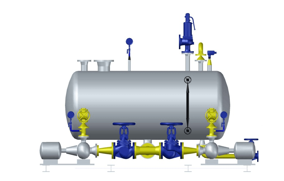
Heat Recovery System
Why Should We Recover Heat from Condensate?
In 1 ton of condensate at 95°C, there is residual thermal energy of 292,600 kJ, which is equivalent to approximately 14 liters of Fuel Oil C. With Fuel Oil C priced at 16 baht per liter, the value of 1 ton of condensate is approximately 224 baht / ton.
If condensate is discharged at a rate of 1 ton per hour, it will result in a significant financial loss of 537,600 baht per year (Note: Operating 8 hours/day, 300 days/year).
If you are interested in reusing condensate to save costs, we are happy to offer a free on-site assessment to provide an investment proposal for a condensate recovery system. We are confident that the payback period for the investment will not exceed 6 months.
If you are interested in a proper condensate recovery system, please contact us at:
- Phone: 085-679-5642
- Email: nakhon@fluidline.net
- Website: https://www.fluidline.net
We sincerely hope to collaborate with you for mutual success at the earliest opportunity.


